
In this shorter post, I will describe a 2X downsampling filter that I propose as a “safe default” for GPU image processing. It’s been an omission on my side that I have not proposed any specific filter despite writing so much about the topic and desired properties. 🙂
I originally didn’t plan to write this post, but I was surprised by the warm response and popularity of me posting a shadertoy with this filter.
I also got asked some questions about derivation, so this post will focus on it.
TLDR: I propose a 8 bilinear tap downsampling filter that is optimized for:
- Good anti-aliasing properties,
- Sharper preservation of mid-frequencies than bilinear,
- Computational cost and performance – only 8 taps on the GPU.
I believe that given its properties, you should use this filter (or something similar) anytime you can afford 8 samples when downsampling images by 2x on a GPU.
This filter behaves way better than a bilinear one under motion, aliases less, is sharper, and is not that computationally heavy.
You can find the filter shadertoy here.
Here is a simple synthetic data gif comparison:
If for some reason you cannot open the shadertoy, here is a video recording:
Preliminaries
In this post, I will assume you are familiar with the goals of a downsampling filter.
I highly recommend at least skimming two posts of mine on this topic if you haven’t, or as a refresher:
Bilinear down/upsampling, aligning pixel grids, and that infamous GPU half pixel offset
Processing aware image filtering: compensating for the upsampling
I will assume we are using “GPU coordinates”, so a “half texel offset” and pixel grids aligned with pixel corners (and not centers) – which means that the described filter is going to be even-sized.
Derivation steps
Perfect 1D 8 tap filter
A “perfect” downsampling filter would preserve all frequencies below Nyquist with a perfectly flat, unity response, and remove all frequencies above Nyquist. Note that a perfect filter from the signal processing POV is both unrealistic, and potentially undesirable (ringing, infinite spatial support). There are different schools of designing lowpass filters (depending on the desired stop band or pass band, transition zone, ripple etc), but let’s start with a simple 1D filter that is optimal in the simple least squares sense as compared to a perfect downsampler.
How do we do that? We can either solve a linear least squares system of equations on the desired frequency response (from a sampled Discrete-Time Frequency Response of a filter), or do a gradient descent using a cost function. I did the latter due to its simplicity in Jax (see a post of mine for example optimizing separable filters or about blue noise dithering through optimization).
If we do this for 8 samples, we end up with a frequency response like this:
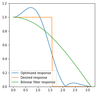
We can see that it is both almost always sharper than bilinear under Nyquist, as well as removes much less of the high frequencies. There is a “ripple” and some frequencies will be boosted / sharpened, but in general it’s ok for downsampling. Such ripples are problematic for continuous resampling filters – can cause some image frequencies to “explode”, but even creating 10 mip maps, we shouldn’t get any problems – as each levels “boost” will translate to different original frequencies, so they won’t accumulate.
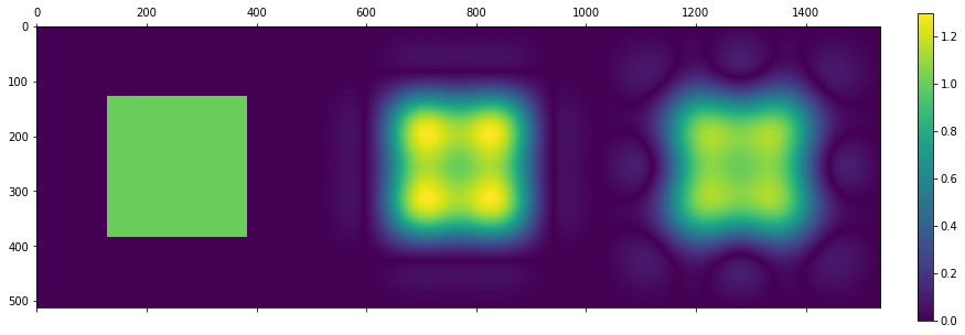
Moving to 2D
Let’s take just an outer product of 1D downsampler and produce an initial 2D downsampler:
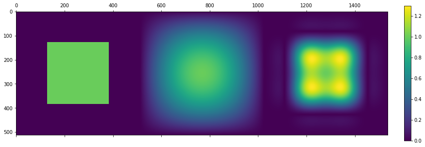
It is pretty good (other than slight sharpening), but we wouldn’t want to use a 8×8, so 64 tap filter (it might be ok for “separable” downsampling, which is often a good idea on CPU or DSP, but not necessarily on the GPU).
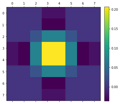
So let’s have a look at the filter weights:
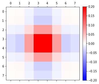
We can see that many corner weights have magnitudes close to 0.0. Here are all the weights with magnitude below 0.02:

Why 0.02? This is just an ad-hoc number, magnitude ~10x lower than the highest weights. But when setting such a threshold, we can remove half of the filter taps! There is another reason I have selected those samples – bilinear sampling optimization. But we will come back to it in a second.
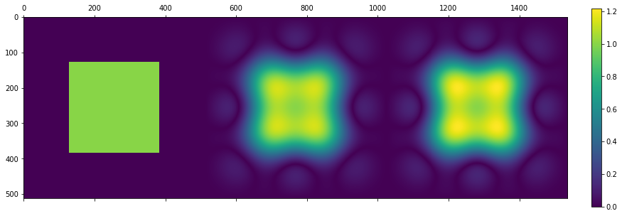
So we can just get rid of those weights? If we zero them out and normalize the filter, we get the following response:
Some of the overshoots have disappeared! This is nice. What is not great though, is that we started to let through a bit more frequencies on diagonals – which kind of makes sense given the removal of diagonal weights. We could address that a bit by including more samples, but this would increase the total filter cost to 12 bilinear taps instead of 8 – for a minor quality difference.
But can slightly improve / optimize this filter further. We can either directly do a least-squares solve to minimize the squared error compared to a perfect downsampler, or just do a gradient descent towards it (while keeping the zeroed coefficients zero). The difference is not huge, only a few percent of difference on least squares error, but there is no reason not to do it:
Now time for the ultimate performance optimization trick (as 32 tap filter would be prohibitively expensive for the majority of applications).
Bilinear tap optimization
Let’s have a look at our filter:
What is very convenient about this filter is having groups of 2×2 pixels that have the same sign:
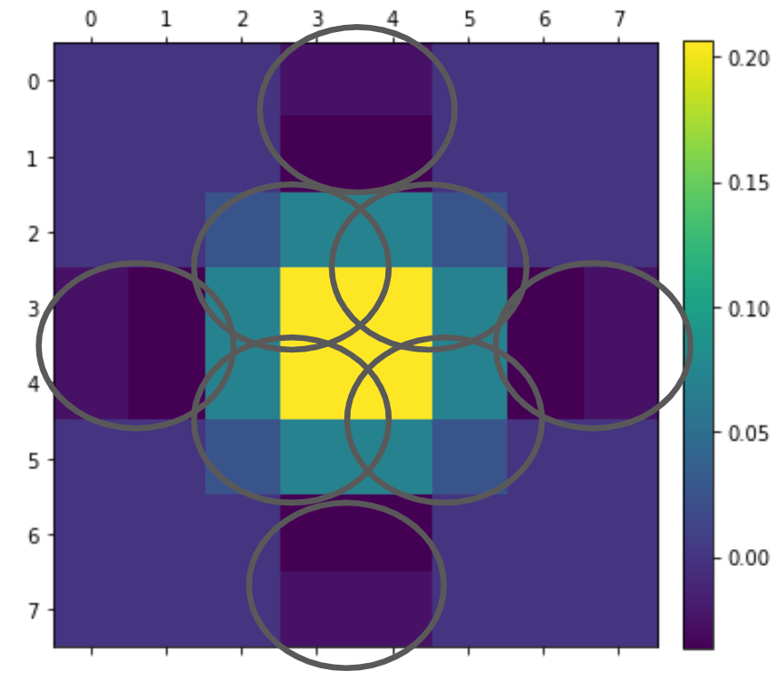
When we have a group of 2×2 pixels with the same sign, we can try to approximate them with a single bilinear tap! This is a super common “trick” in GPU image processing. In a way, anytime you take a single tap 2×2 box filter, you are using this “trick” – but it’s common to explicitly approximate e.g. Gaussians this way.
If we take a sample that is offset by dx, dy and has a weight w, we end up with effective weights:
(1-dx)*(1-dy)*w, dx*(1-dy)*w, (1-dx)*dy*w, dx*dy*w.
Given initial weights a, b, c, d, we can optimize our coefficients dx, dy, w to minimize the error. Why will there be an error? Because we have one less degree of freedom in the (dx, dy, w) as compared to the (a, b, c, d).
This is either a simple convex non-linear optimization, or… a low rank approximation! Yes, this is a cool and surprising connection – we are basically trying to make a separable, rank 1 matrix. 2×2 matrix is at most rank 2, so rank 1 approximation in many cases will be good. This is worth thinking about – which 2×2 matrices will be well approximated? Something like [[0.25, 0.25], [0.25, 0.25]] is expressed exactly with just a single bilinear tap, while [[1, 0], [0, 1]] will yield a pretty bad error.
Let’s just use a simple numpy non-linear optimize:
def maximize_4tap(f):
  def effective_c(x):
    dx, dy, w = np.clip(x[0], 0, 1), np.clip(x[1], 0, 1), x[2]
    return w * np.array([[(1-dx)*(1-dy), (1-dx)*dy], [dx*(1-dy), dx*dy]])
  def loss(x):
    return np.sum(np.square(effective_c(x) - f))
  res = scipy.optimize.minimize(loss, [0.5, 0.5, np.sum(f)])
  print(f, effective_c(res['x']))
  return res['x']
Note that this method can work also when some of the weights are of differing sign – but the approximation will not be very good. Anyway, in the case of the described filter, the approximation is close to perfect. 🙂
We arrive at the final result:
    vec3 col = vec3(0.0);
    col += 0.37487566 * texture(iChannel0, uv + vec2(-0.75777,-0.75777)*invPixelSize).xyz;
    col += 0.37487566 * texture(iChannel0, uv + vec2(0.75777,-0.75777)*invPixelSize).xyz;
    col += 0.37487566 * texture(iChannel0, uv + vec2(0.75777,0.75777)*invPixelSize).xyz;
    col += 0.37487566 * texture(iChannel0, uv + vec2(-0.75777,0.75777)*invPixelSize).xyz;

    col += -0.12487566 * texture(iChannel0, uv + vec2(-2.907,0.0)*invPixelSize).xyz;
    col += -0.12487566 * texture(iChannel0, uv + vec2(2.907,0.0)*invPixelSize).xyz;
    col += -0.12487566 * texture(iChannel0, uv + vec2(0.0,-2.907)*invPixelSize).xyz;
    col += -0.12487566 * texture(iChannel0, uv + vec2(0.0,2.907)*invPixelSize).xyz;
Only 8 bilinear samples! Important note: I assume here that UV is centered between 4 high resolution pixels – this is the UV coordinate you would use for bilinear / box interpolation.
Conclusions
This was a short post – mostly describing some derivation steps. But from a practical point of view, I highly recommend the proposed filter as a drop-in replacement to things like creating image pyramids for image processing or post-processing effects.
This matters for low resolution processing (for saving performance), or when we want to create a Gaussian-like pyramid (though with Gaussian pyramids we very often use more heavily lowpass filters and don’t care as much about preserving exactly below Nyquist).
If you look at the stability of the proposed filter in motion, you can see it is purely superior to box downsample – and not sacrificing any sharpness.
Bonus – use on mip maps?
I got asked an interesting question on twitter – would I recommend this filter for mip-map creation?
The answer is – it depends. For sure it is better than a bilinear/box filter. If you create mip-maps on the fly / in runtime, like from procedural textures, then the answer is – probably yes. But counter-intuitively, a filter that does some more sharpening or even lets through some aliasing might be actually pretty good and desireable for mipmaps! I wrote how when we downsample images, we should be aware of how we’re going to use them – including upsample or bilinear sampling, and might want to change the frequency response to compensate for it. Mip-mapping is one of those cases where designing a slightly sharpening filter might be good – as we are going to bilinearly upsample the image for trilinear interpolation or display later.

Hello! Thank you for another great read and all the information contained in it. I would have a few related questions on this topic.
In the first figure of the Moving to 2D section, that green square representing the perfect downsampler frequency response, isn’t the perfect downsampler supposed to be a circle instead of a square? Like taking a 1D sinc function and rotating it around it’s center axis, doesn’t using a square mean that diagonals are treated differently from vertical and horizontal lines?
Since you talked a bit about texture filtering with linear interpolation (with mip-maps), why are so many developers still using linear interpolation instead of higher order one for this? From what I know, there have been quite a number of papers showing how to achieve higher order for little or no extra cost compared to linear, here’s just one example of such a paper:
https://dl.acm.org/doi/10.1145/3306346.3323032
So why is linear interpolation still so widely used even after all these years, is there something hardware related to it?
About anti aliasing resolve filters, since you talked in the past about taking human perception into account, here’s an interesting question, back in the old days of DirectX 9 and 10, I remember that a lot of people including many game developers liked the averaging filter (the box filter) the most out of all the common resolve filters. Just applied 8x (or more) sparse grid anti aliasing and then resolved with box filter. We know that the box filter is a leaky filter that oscillates to infinity in the frequency domain since it corresponds to a sinc function in the frequency domain.
This gets shown here at slide 60:
https://slideplayer.com/slide/14583857/
And also gets detailed here at pages 18-19:
Click to access CG08%20-%20Sampling%20and%20Reconstruction.pdf
And also gets shown here at page 4 (page 6 from pdf), figure 2:
https://www.researchgate.net/publication/245425420_Antialiasing_with_Stratified_B-spline_Filters_of_Arbitrary_Degree
Yet, even like this, everyone seemed to like it the most. We know that human vision is somehow naturally attracted to the higher frequencies and to sharper objects and images, could it be that because the filter is so leaky it retains some sharpness compared to many other filters and this extra sharpness makes it more appealing to so many? I’m guessing that one and the fact that it doesn’t have much issues with the DC component of an image are the two things that make it somehow appealing to the human vision compared to other filters, even with all of the flaws.
What I mean by the DC component is from this old and still very good paper:
Click to access Mitchell.pdf
And my last question, anti aliasing seems to be the one area from graphics where, even after all of these years, it somehow still doesn’t get done right and there are still tons of issues, do you think there’s any chance of getting anything like primitive filtering being done in real time in the near future? I’m talking here about the only true way to actually solve aliasing for good, which is to prefilter the signal prior to sampling, there was even an older paper on this:
https://diglib.eg.org/bitstream/handle/10.2312/PE.VMV.VMV13.169-176/169-176.pdf?sequence=1&isAllowed=y
I wonder, is something like this ever becoming a reality for real time applications?
Or perhaps cone tracing would also achieve a similar effect to prefiltering primitives?
Hi Vlad, thanks for great questions!
I’ll try to answer the ones I feel competent answering.
1. For the 2D case and desireable frequency, the goal of anti-aliasing pre-filters is to remove all frequencies that are not representable after resampling. In the case of 2D grid, Nyquist frequencies are bounded by a square – due to separability of sampling. And yes, it means that more diagonal frequencies are representible. I even had an older post on how this is used by checkerboard rendering:
The circularly symmetric filter is known as “jinc” and sometimes is proposed for *upsampling* for slightly smoother diagonal edges (getting rid of “teeth” on them) – but generally it also slightly softens textures and the opinions on it are mixed. It’s very very rare to see its use – it’s not separable and has significant cost. I sometimes used it for upsampling – but never for downsampling, as removing more frequencies than necessary when you are already throwing out a lot would reduce sharpness quite a bit…
2. I am always dubious about the claims of “free” higher order interpolation. It is impossible to get it without extra memory – just because cubic order by definition needs 16 values from the memory – and from GPUs perspective, touching memory (and holding it into cache etc) is what is expensive.
On one project I worked on, getting even biquadratic into hardware (this was for an ASIC) was a big ask from hardware engineers. Apart from it, there are more issues – how would it behave with anisotropic sampling, sampling cubemaps, 3D textures? This is a lot of super complicated silicon. On top of it, it would need to be standardized by APIs (or exposed by extensions), and they would need to either agree on “which” cubic to implement, or add coefficient controls into the sampler…
Generally, I think the philosophy of designing hardware like GPUs is to build special hardware and circuitry for things that are either impossible to do without, would be very expensive power-consumption wise, or basic building blocks. Bilinear is a super basic block that can be used to build more complicated samplers.
3. I think it wasn’t necessarily that people liked the box filter the most, but: 1. many game developers didn’t know any signal processing or alternatives 2. Any reasonable filter needs to read samples from outside of the pixel footprint, which was too expensive for hardware implementations like MSAA. 3. Some indeed didn’t like Gaussian reconstruction filter for being too soft, this kind of makes sense with older, lower resolution displays.
Offline rendering have used variants of Mitchell filters and not the box – because they had more computational budget and simply spent time working on this problem.
4. Geometric aliasing is not great, but it is not the only source of aliasing. As big of a problem is all kinds of shading aliasing (most visible on specular), shadowmap aliasing, Monte Carlo techiques aliasing and noise. Therefore any solution that addresses only geometry aliasing is not very attractive, as one needs to still address other types of aliasing, prefilter textures, prefilter shading etc. We would want to filter the integral lighting x shading, but this gets even more difficult! This is why temporal supersampling got so popular – as it addresses all types of aliasing.
But I also think there is a problem with knowledge of aliasing and signal processing – and propagating some knowledge is one of the reasons why I write my posts. 🙂
Some techniques like voxel cone tracing can indeed prefilter both geometry and radiance – but are limited in many other ways and slow…
Hello! Sorry for being so late with this, I’ve been trying to post this answer for almost a week now, somehow it didn’t really work at all, hopefully it gets posted this time around.
Thank you a lot for the answers!
Your answers here have been very detailed and easy to follow!
1. I understand what you mean here about the separability of sampling with a rectangular grid, I’m guessing that if the Nyquist frequencies are bounded by a circle, then that must mean non-separability. I was thinking this way since the perfect brickwall filter (the sinc) is both kind of related to the Gaussian in some ways (both of them are infinite in length and both are mathematically non-separable for the multidimensional cases), yet they are also the opposite of one another since the Gaussian is the “perfect” time/space domain filter and the sinc is the “perfect” frequency domain filter. And since a true Gaussian filter is non-separable in the true mathematical sense, I used to think of the multidimensional sinc filter in pretty much the same way, obviously not a good idea here in the context of separable sampling, I get that now. And also on this whole separable sampling topic, I’m really surprised that hexagonal sampling patterns get so little use even after all these years, I mean the theory behind is pretty clear that the hexagonal pattern is the “optimal” sampling pattern for 2D signals and much better than the rectangular pattern, not to mention the tons of other advantages that it brings like better sampling density, least quantization error, Fourier transform that is still hexagonal, higher symmetry, consistent connectivity, greater angular resolution, equidistant neighboring pixels, and so on. Even with image sensors the hexagonal pattern was really good when rarely used, the Sony Cinealta F65 camera is one of the very few examples of sensors that used a somewhat hexagonal pattern (some people say it was hexagonal, some say it was a kind of a rotated pattern, in reality it was a little bit of both) and that sensor did really well in aliasing tests and all around resolution.
2. I totally get what you mean here about higher order interpolation and just how much work it would take to standardize it somehow. About adding coefficient controls into the sampler, I’m not sure if that is so hard to do considering that in the past ATI have done something like this for their RADEON lineup many years ago when they had those programmable anti aliasing resolve filters. At first I remember that they used a lot of custom and dedicated hardware, but after some time they scraped all of that and simply moved most of the calculations into the shaders and that opened the possibility for some even higher quality filters, long time since then. So I’m not sure here how hard it would be to do something like this these days, but probably there is very little interest in this topic from the industry.
3. You’re definitely right here on this one, many developers back then didn’t properly understand signal processing and that combined with the lower resolution screens of back then is probably why the box filter had such a long life as a resolve filter.
This topic was probably endlessly debated before, but I’m curious, in what space do you think the resolve filter should be applied, should it be in linear space, or should it be in a perceptual space (gamma or otherwise)?
I definitely agree that for offline rendering a much better solution is needed than with box, the variants of Mitchell are a much better choice. In my opinion, the best and still somewhat practical resolve filter would be one that has linear phase, doesn’t have issues and artifacts with the DC components in the images, and the rest is a good compromise between amplitude-frequency response and phase invariance, and then after this filtering following with sharpening for high frequency recovery since the sharpening will not reintroduce aliasing as long as it is inside the window of the resolve filter used. And of course making sure to set and allow for the negative mip bias in order to match the number of used samples and the used pattern, in my opinion this whole approach produces a very solid and consistent image quality, or at least from the family of “simple” resolve filters, not counting the really complex or complicated solutions, or machine learning ones.
4. I think it is pretty safe to say that there are six major types of aliasing in graphics, these have to be the geometry aliasing (bad looking edges, jaggies), transparency aliasing (transparent objects and textures), sub-pixel aliasing (when objects, details, features, etc become too small and don’t show even if they are supposed to), shader aliasing (probably the worst one), texture aliasing (should be solved in theory by mip-mapping and texture filtering), and finally temporal aliasing (all sorts of things like flicker, weird motion, false movements, etc). Now each of these would require a very specific approach in order to take care of the issue. I know temporal anti-aliasing techniques are by far the most popular ones today, but I just can’t stand them at least half the time (or maybe I can’t stand the way they are often poorly implemented) and I’m still not convinced they can be reliably implemented, for instance, how do you do temporal anti-aliasing for objects that change their shape in every single frame compared to the previous ones, I’m not saying it can’t be done, but I’m guessing the effort here for this would be colossal and still have artifacts in the end. I’m not saying temporal methods and techniques aren’t any good, or that they should be avoided, just saying that they shouldn’t probably be used for almost everything like they are today, they do have their uses and are very good at that, but not fixing everything.
I very much appreciate what you’re trying to do here with all your posts propagating some real knowledge and with a very engineering driven approach, this is always a very good idea!
Alright. What’s about resilience to non-square and non-power of two input image data. Practical example: generation full mipmap sequence for texture of any resolution. More specific 903×451. Next mipmap will be 451×225. Could it be a problem for filter above because this requirement:
>> I assume here that UV is centered between 4 high resolution pixels – this is the UV coordinate you would use for bilinear / box interpolation.
If it’s a problem what do we need to do?
Yes, it would be a problem. If you are resizing by a non-integer factor, every texel needs different filter weights. They can be recomputed per texel, but it would be drastically slower.
A different, pragmatic solution is to either add padding, or clip the texture so it is divisible by 2.
This is the reason why general art creation guidelines ask artists for only pow2 texture sizes…
Thank you for clarification.