
Almost every graphics programmer I know is playing right now with some electronics (virtual high five!), so I won’t be any different. But I decided to make it “practical” and write something that might be useful to others – how I modded a Korg MS-20 Mini.

The most important ones are a PWM mod input – a quick phone video grab here (poor quality audio, demo only, might upload separately recorded MP3s later):
And oscillator sync together with a oscillator 2 FM input:
I am not taking any credit for the invention of the described modifications, but I am going to cover in some more detail as compared to the previous sources.
Korg MS-20
Korg MS-20 mini is a reissue of the legendary synthesizer from Korg which was made in 1978 (!) as a cheap alternative to super expensive Moogs of that era. It has two extremely “dirty”, screeching filters that was made famous throughout the emerging electronic music scene and where distorted, aggressive sound fit perfectly. It has also a very non-linear behavior and weird interactions between the lowpass and highpass filters when their resonance is cranked up, making it a very hands-on type of gear with many cool sounding sweet spots.
I mean, just look at the wikipedia list of its notable users:

From organic “Da Funk” of Daft Punk, through dirty blog house electro of MSTRKRFT, The Presets, and Mr Oizo, broken beats of Aphex Twin, to pulsating rhythms of the Industrial EBM sounds of Belgian and German artists of the 80s – this is an absolute classic, in many genres exceeding the use of Roland Juno’s or Moogs.
It was both super affordable (well you know… most bands bands on that list are not prog rock millionaires who could have afforded Moog or Roland modular systems, or even Minimoogs 🙂 ), and just sounds great on its own.
I tried some emulations and thought they were pretty cool, but nothing extraordinary, but when I visited my friend Andrzej and we jammed a bit on it + some other synths, I knew I need to get the hardware one!
Semi-modular architecture allows for great flexibility and some “weird” patching and exploration of sound design and synthesis (it’s easy to synthesize whole drumkit!), and the External Signal Processor is something extraordinary and not heard of anymore.
There are a few quirks (the way its envelopes work), and notable limitations though as compared to modern synths – but some of those limitations can be “fixed”! The lack of PWM control of the square/pulse wave, lack of oscillator sync, lack of flexible oscillator wave mixing for the first oscillator, and lack of separate frequency modulation of the second oscillator.
Modding MS-20 – sources
Luckily, the synth has been around for such a long time that many have explored extremely easy mods to allow for that and it’s pretty well documented.
I have followed mainly the Korg MS-20 Retro Expansion by Martin Walker, who in turn expanded on the work of Auxren: MS-20 Mini PCB Photos and OSC Sync Mod, MS-20: PWM CV In and Passive 4X Multiplier.
Please visit those links, and check out their diagrams, which I’m not going to re-post out of respect for the original authors.
I used them as my guidance and definitely without them would not have been able to mod it.
That said, Martin Walker’s description had a tiny bug in the text (diagrams and photos are rock solid and greatly valuable!), and Auxren didn’t cover the most exciting (to me! 🙂 ) Osc2 FM mod essential to make the oscillator sync sound like its most common modulated uses.
One of the mods – PWM input jack – is extremely easy. It requires less disassembly, soldering is trivial. Similarly separate oscillator outputs. Those I can recommend to almost everyone.
The other ones are a bit more tricky and involve soldering to the top of tiny surface components.
Required components, tools, and skills
Here’s a list of minimum what you need to have (apologies if I didn’t get all the tool names right, English is not my native language):
- A set of screwdrivers. Among those you’d probably want something pretty small and short, some unscrewing is inside of the synth with limited space.
- A driller with a set of metal drills to drill the holes for pots and jacks. Step drills are an option as well if you know how to use them.
- A set of wrench keys. Surprisingly not as useful as I thought (more on that later).
- Soldering kit. Hopefully you have a good one already!
- A decent multimeter and potentially a component tester.
- Some optional clamps / holders. This makes a lot of steps easier and safer.
- Safety goggles and gloves for drilling.
- Some non-electrostatic (if possible) cloth to put components safely on.
- Small wire cutters.
- Some sanding paper.
You will need to buy / have / use as components:
- 5 mono minijack (3.5mm jack) sockets.
- Two 100k resistors, one 10k resistor. But it wouldn’t hurt just buying some resistor set.
- A mini toggle switch (on/off, 2 pins are enough).
- A single diode like 1N4148 or similar – doesn’t really matter.
- Three 100k mini potentiometers. Martin suggests log taper (type A), but I’d probably suggest two type A for the volume, and one type B linear for the FM mod intensity.
- Bunch of colored cables.
Finally, I’d say that if you have never soldered before, I would advise against modding a few hundred dollars (even if bought second hand…) synth that has tons of tiny components, and you’d need to solder to some of the surface-mounted extremely tiny and fragile spots.
If anything, stick to the relatively easy PWM mod.
You can very easily burn off the parts of PCB, make tin drops that will connect things that are not supposed to be connected together…
Despite the very small amount of soldering required, this is rather not a starter DIY project – but I won’t say it’s impossible (I don’t want to gatekeep anyone, and learning by doing with some extra “pressure” is also fun). But I’d still recommend first soldering together a guitar pedal or delay effect and practicing soldering in general, knowing what are the potential issues etc.
Opening it up
Before opening any piece of hardware, the most important advice:
Always take photos of everything you are about to disassemble.
Always place all the parts separately and clearly marked.
This will remove quite a lot of the stress of “figuring out how to put it back together”.
The first step (that I did a bit later and it doesn’t matter, but it’s easiest when done first) – take off all the knobs. Large ones come off easily, smaller ones take some delicate pulling from different sides. Don’t use a screwdriver to lift them, they are made of quite delicate plastic and you could damage it!

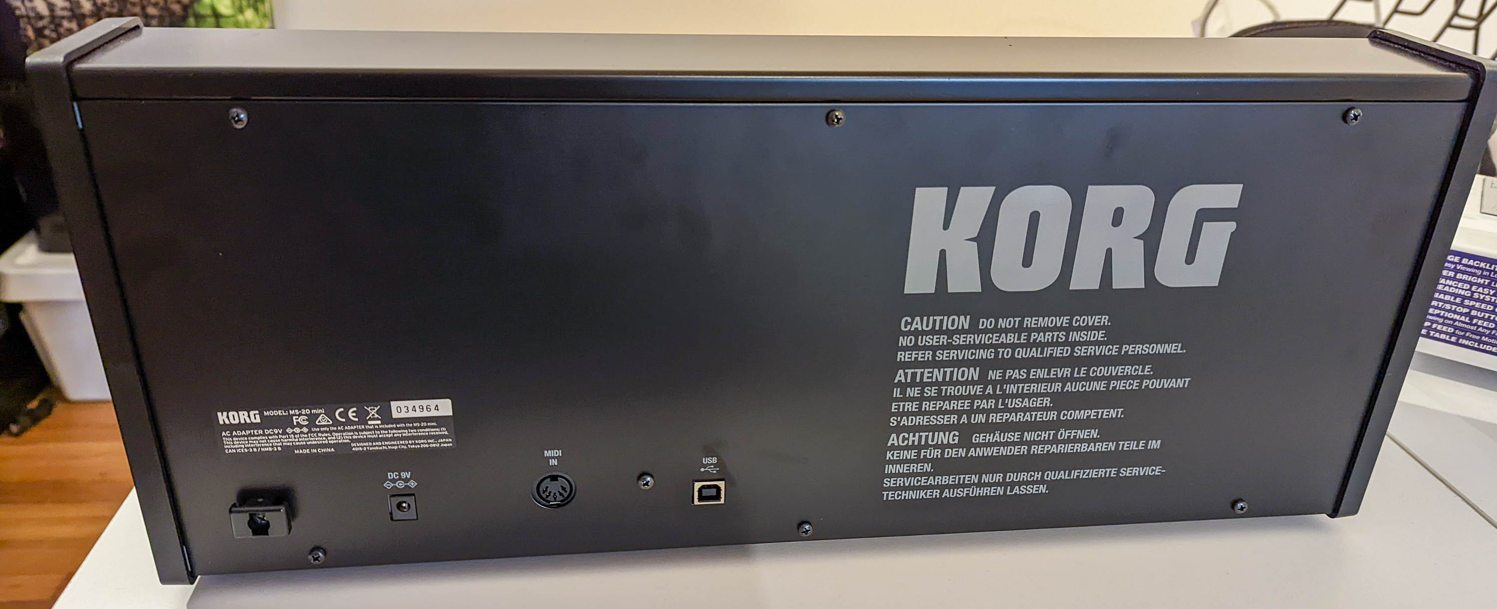
Important note: unfortunately, the silver jack “screws” are a decoration. I tried taking them off using a wrench only to realize I’m breaking some plastic. 😦 Leave those in place. I was disappointed at the quality of this and the cost cutting measures… Other than that, MS-20 mini is built well and very smart (in my very limited experience).
Unscrew however with a wrench key the plastic black headphone minijack.
I suggest taking off one of the sides (I took off the one closer to the patchbay), and the back screws.


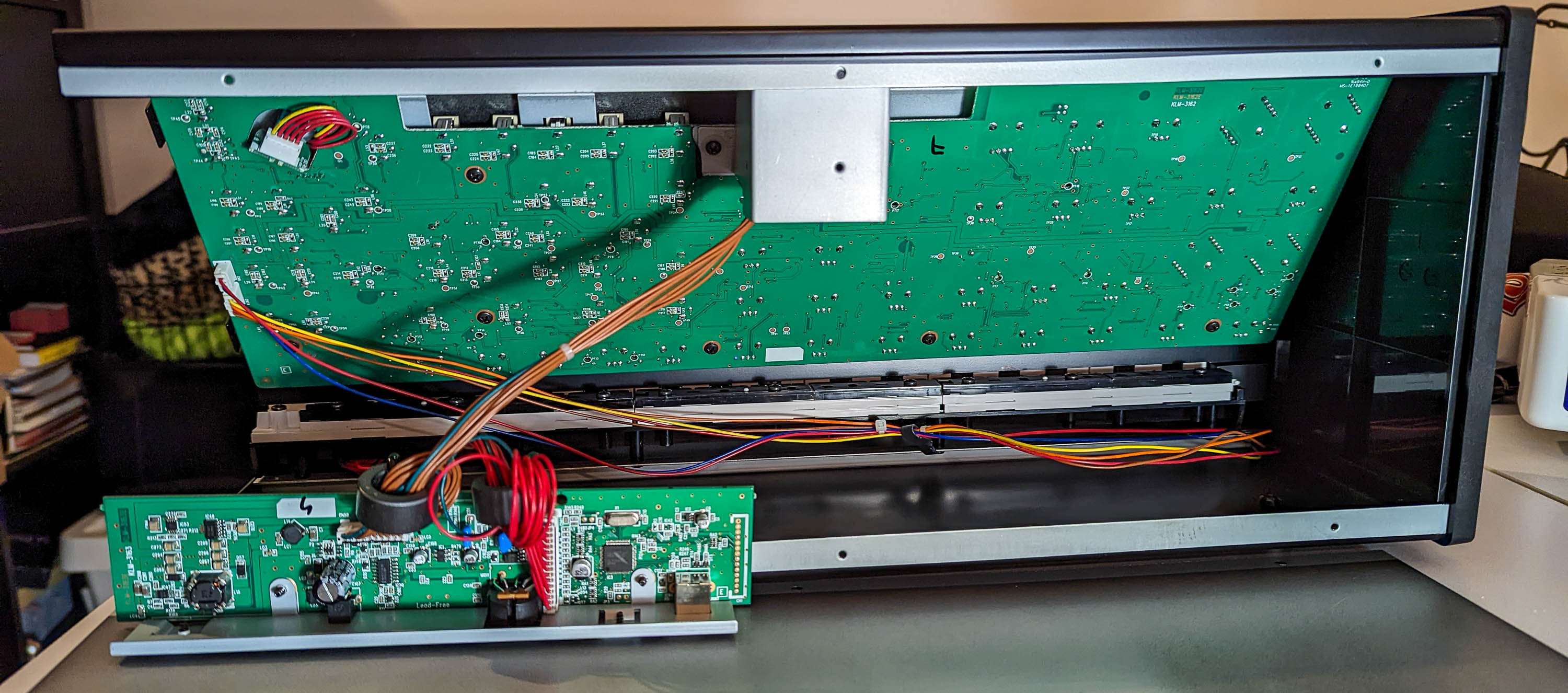
This is how it looks like inside, with its back taken off:
Now, the cool part is that to do just the PWM input mod, you don’t need to disassemble anything anymore! Just solder the cable to the back of the board in the required point (described later) and you’re done!
If you want to go with the other mods, then you need to take off some more screws. Those include some on the other side (you will see which ones), as well as this annoying metal piece that holds everything more stable:

It’s annoying as I later needed to trim it due to my incorrect pot placement, and it is a bit hard to reach, but you should have no problem.
After it and a few screws on the surface, the main board is disassembled, very carefully (watch out for the connected keyboard cables!) put it down:
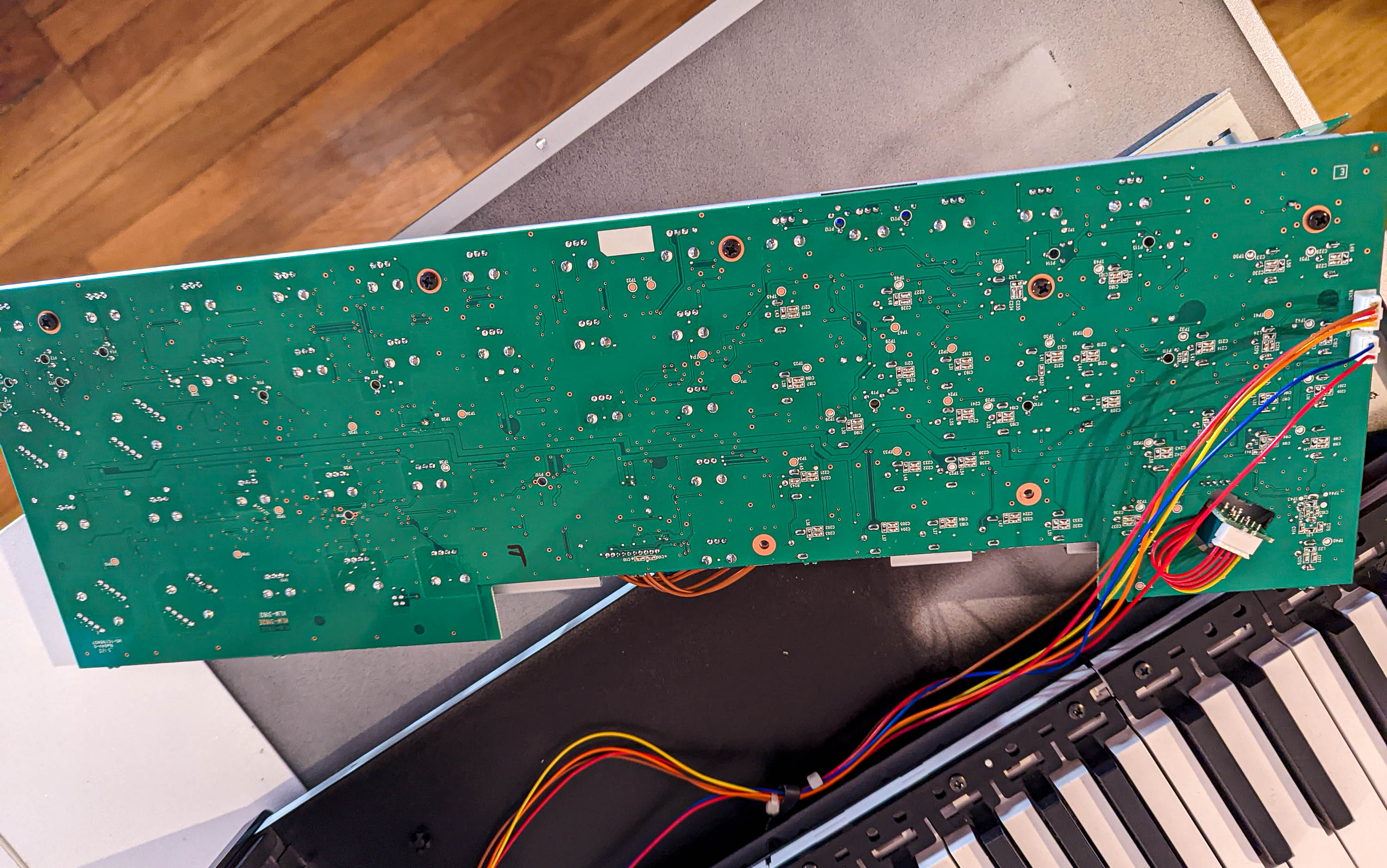
Finally, you’ll need a wrench key to take off the nuts holding pots onto metal grounding shield:
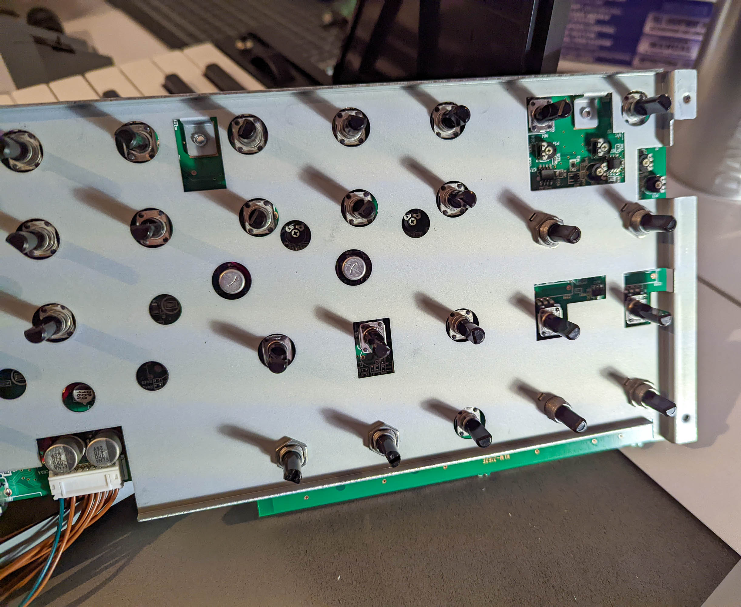
And voila, Korg MS-20 mini (almost) disassembled!

Soldering wires
Ok, so now for the tricky part – soldering.
On the back it’s almost trivial:

You solder to one of the ground points (black cable), there are plenty of those, to the pulse width pot (purple cable), and to three middle legs of the oscillator wave selection switch.
On the front, things get trickier:

The osc sync requires soldering two cables at two diodes, marked on my picture with red and yellow – D4 and D7. D4 is an annoying one, you need to solder very precisely between some other components.
Virtual mixing ground for inputs is purple cable at IC14 op-amp.
Finally, for the oscillator 2 FM mod, you need to solder to R183 (green cable). This is where Martin’s diagram is correct, but his text (mentioning soldering to the wiper of the potentiometer) is a bit wrong.
The orange cable was there and was not soldered by me. 🙂
At this point, I suggest double checking every spot, testing it around with a multimeter (with the synth power off and disconnected, at least as the first step) if you didn’t short anything.
Drilling holes and mounting pots
Unfortunately I didn’t take photos from my drilling process.
It’s pretty standard – mark the spots using a ruler and some sharp piece “puncturing” the paint there, and progressively drill with first small, and then larger and larger drills, until your switch/pots/jacks go through without a problem. You can use step drills, I even bought some, but decided to not use them (as I have never used those before).
After each step, clear everything up from scraps, make sure everything is solid mounted, and at the end optionally sand-paper around it.
Now, other than a few scratches (that I have no idea how happened, but those don’t bother me personally too much…) I made a more serious mistake in my hole placement.
The problem is that this placement:

Is too far to the left by ~1.5cm (more than half an inch). 😦 This made putting it back problematic with this part:

This is not visible on the picture, but inside, it has metal piece that touches the upper part. And for me it was overlapping with the mini switch and mini jack socket… So I had to cut it slightly. I don’t think it’s a problem – everything worked out well, it holds well, but it was stressful, and be sure to verify the dimensions / sizing.
After your pots and jacks are in place, get back to soldering. I suggest starting with connecting all the grounds together – you are going to need a lot of cables there and be smart about their placement to not turn it into a mess.
It’s much easier to do it when you don’t have everything mounted together and other cables “dangling” around. Then solder the diode and the resistors to the legs of the switch / potentiometers.
At the end finally solder the cables from the mainboard – and be careful at this stage to not “pull” anything.
Putting it back
Before you put everything back together, I suggest very carefully, taking care to not short anything and with proper insulation, turn the MS20 on and start testing. Does it work as expected with the basic functionality? Is the new functionality working?
(Internally, it uses 18V max, so it’s not very unsafe for yourself, but still be careful to not fry the synth!)
If it does (hopefully in the first go!), time to start putting everything together. In the meanwhile, at two more steps (after putting the main board in its place, and after screwing everything except for the back) I still tested if everything’s ok.
Final results
Overall it took me a few whole evenings (a few hours each).
Generally I wouldn’t expect this to take less than ~2 days, unless you know exactly what you’re doing and you’re less scared of screwing something up than I was.
It was stressful at times (soldering), but other than a few scratches that you can clearly see on my photos, everything turned out well.
Ok, so this is again how the synth looks like now (oops, didn’t realize it’s so dusty):

It was a super fun adventure and I love how it sounds! 🙂
I was also impressed with how one puts together such a large, “mechanical” construction – mostly from plastic and cheap parts, but other than faux jack covers, built really well.

Regarding the individual outs – how have you grounded the sockets?
Have tried following your instructions and got it working, but no longer normaled through the MS20. Needs a dummy jack in the outs, or to be re-routed through external in…
This shouldn’t be the case for sure. I would check the type of the jacks and their normalling – and whether you soldered them so that everything is disconnected when no jack is present. Without a jack, there is no closed circuit, so the modification should do nothing to the original sound… (For me it retains 100% original functionality without any plugs)
Where do the two 100k and 10k resistor go? Thanks for your time.
I followed the diagram on http://www.yewtreemagic.co.uk/soundworlds3.php – one goes to the wiper of FM pot, other ones to the wipers of remaining new added pots.