In this blog post, I will present some common spotlight culling techniques and propose one small improvement that is able to correct results of cheap, tiled / clustered culling on the CPU/GPU with almost negligible ALU cost. If you know a lot about tiled light culling, feel free to skip till the last section.
The idea for this post came from the fact that many people talking about light culling talk mostly about spherical point lights. However in many practical applications point lights are actually rare! It is not uncommon to implement even point light rendering and their shadow casting not through cubemaps for shadowmaps, but through 1-6 clipped spot lights (getting the advantage of being able to vary their resolution, cull intersecting geometry separately and compute optimal near/far planes).
Main problem with culling spotlights is that unlike spherical / point lights, many widely used tests cause some overdraw / false positives. With physically-based correct light falloffs and BRDFs, light can get really huge (specular component can be seen very far away) and most common tests are not suited for culling of large primitives. I will have a look at few possible techniques in following sections.
Note: in sample code you will see instructions like sin or cos – obviously you don’t want to call them, but precompute them ahead – this is only for demonstration purposes.
You can find Mathematica notebook that comes with this post here and the pdf version of it here.
Introduction / assumptions
Talking about generic collision tests of spot lights, I am going to approximate them as cones (extra cap is easy to add; in most of those tests it can be skipped though). I will talk about culling them against mini-frustums with focus on tiled lighting – tiled deferred and clustered forward lighting – but they apply in theory to any kind of culling technique. In theory it could also be applied to tiled forward+ for transparent object lighting, however it won’t benefit that much from some of mentioned optimization techniques due to very long frusta. In those cases it is better to use clustered shading anyway! In general, clustered shading is preferable and can be made extremely efficient with some low level hardware tricks, for example as presented by Tiago Sousa and Jean Geffroy.
In most of this post, I will assume that tile frustum is not extremely long, so has relatively uniform dimensions. While it could be considered limiting, in practice it is possible to achieve that assumption even withing just classic tiled deferred by splitting tiles depth bounds based on the depth distribution.
I will also demonstrate ideas here in 2D for simplicity, but they extend one to one to 3 dimensions (unless noted otherwise).
Simple approach – cone as a sphere
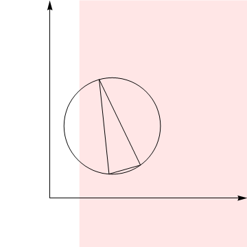
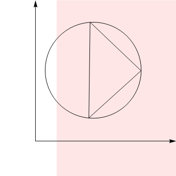
First approach is quite trivial. Instead of dealing with a spotlight / cone, we can have a look at its bounding sphere. Obviously taking equivalent pointlight bounding sphere would be extremely wasteful, so instead we want to find an exact bounding sphere of a cone. To find it, we can have a look at just 2 cases: either triangular cone slice is obtuse or not.
Cone slice bounding sphere
In case of obtuse triangle, bounding sphere’s center will be on the cone cap with radius equal to the radius of the cap. In the acute case, we want to find a circumscribed triangle. There is a very easy formula for finding one based on one of triangle angles and length of opposite side, it is A / sin(a). After taking into account half angle and half-diameter and doing some trigonometric reductions, it becomes trivial 1/(2cos(halfAngle)).
float4 boundingSphere(in float3 origin, in float3 forward, in float size, in float angle)
{
	float4 boundingSphere;
	if(angle > PI/4.0f)
	{
		boundingSphere.xyz = origin + cos(angle) * size * forward;
		boundingSphere.w   = sin(angle) * size;
	}
	else
	{
		boundingSphere.xyz = origin + size / (2.0f * cos(angle)) * forward;
		boundingSphere.w   = size / (2.0f * cos(angle));
	}

	return boundingSphere;
}
This can fail in many situations even with a simplest plane vs sphere tests:
However in some it will work reasonably well against a single plane. Having precomputed the spheres on the CPU or just ahead of time, it is extremely cheap test to perform.
Unfortunately, this test it suffers from a “corner” problem typical to all primitive vs planes partial swept line tests:
Here is a stop frame from this animation, you can see how every plane test succeeds and cone / sphere are not culled by any of them, so the whole bounding sphere cannot be culled:

Thomas Gareth proposed a simple trick / workaround: precise, Minkowski sum culling of a sphere against bounding box of the frustum.
Here is how it performs in the same case, simple and cheap box test against the sphere gives expected result without false negatives:

Different approach – plane cone tests
While not forgetting about frustum planes test failures, we can try addressing those very thin or very wide cones with better plane vs primitive collision test and see how it’d work in practice.
The main idea is simple – find a closest point on the primitive to the plane and test it against that plane. In 2D this is trivial – the point will be the closest one of 3 triangle corners:
3D case
In 3D it gets a bit more tricky, but same assumptions remain. But this time we either test the cone apex or closest point on the cap rim. Idea one might to do it efficiently comes from Christer Ericson’s book “Real-Time Collision Detection”.
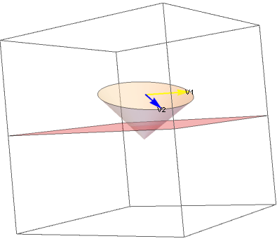
Let me visualize first how the algorithm works:

We are trying to find vector V2 that is closest to the plane surface. To do it, we first compute a vector V1 that is perpendicular to both plane normal and the cone “forward” vector. This can be done by performing a simple cross product. We also get a guarantee that this vector will be on the cone cap (since cone cap plane has all vectors perpendicular to cone axis). Then we do yet another cross product with the cone axis – to get a vector perpendicular to both the cone axis (so it will still be on the cone cap) as well as this vector perpendicular to the plane normal. It means it will be a vector that points in direction most similar to the plane normal or in the opposite direction, depending on the order of cross product operations.
It is very important here to not forget a “safe” normalize, since depending on the sine of the initial angle between plane normal and the cone orientation, result can be a very short vector. If it is zero, we can totally ignore it as it means that cone cap is parallel to the plane and we need to only check the apex.
Here we can see how this works in practice for a test that detects an intersection:

Finally, we need to also check the cone origin point – since cone cap can be quite far away from the plane, but the cone intersect it anyway:
We can code it easily in hlsl for example like this:
bool TestConeVsPlane(in float3 origin, in float3 forward, in float size, in float angle, in float4 testPlane)
{
	const float3 V1 = cross(testPlane.xyz, forward);
	const float3 V2 = cross(V1, forward);

	const float3 capRimPoint = 	origin +
								size * cos(angle) * forward +
								size * sin(angle) * V2;

	return dot(float4(capRimPoint, 1.0f), testPlane) >= 0.0f || dot(float4(origin, 1.0f), testPlane) >= 0.0f;
}
Back to a 2D example
How does it perform? In theory it could be better (we can get much closer than the bounding sphere and still get some culling), but it is still suffering from the same problems like all frustum plane tests:
In practice, this is a huge problem. Just have a look in a a little bit contrived scenario of a regular grid:
This looks almost totally useless!
There are few solutions to it. I will mention first a heavy / complicated, but best solution, suggested by Matt Pettineo – rasterizing the cone in tested space and then either simply checking against this rasterized mask, or doing proper, rasterized computation of tile / cluster bounds in 2D. It is not so easy to implement, requires smart tricks to work around lack of conservative rasterization on most available consumer hardware and adds extra passes to the rendering pipeline. I would suggest doing it this way if you have time, but I will propose a bit coarser, but very cheap and simple solution if you don’t.
Flipping the problem
In the idea I propose (I am sure it is not new/revolutionary; however haven’t seen it in any published material related to tiled light culling) I got inspired by both Thomas Gareth and Inigo Quilez. Instead of doing partial separating axis test by testing frustum planes, in case of small frusta against large primitives, we should do the opposite!
Just test the cone against some other primitive.
What other primitive? The easiest one; a sphere – their symmetry makes Minkowski-sum tests quite trivial. Just find a furthest point on the tested primitive towards the sphere center and perform a distance check.
Here is how it would work geometrically:
We can see a vector V that goes from cone origin towards the sphere. Then this vector V is decomposed into perpendicular vectors V1 and V2. V1 is projection of V onto the cone axis that is clipped against cone axis length, while V2 is V minus the projection – clipped against tan(coneAngle) times V1 length.
This way we get a point that is closest to the cone and we can simply check the distance of this point from the sphere center against the radius of the sphere. Note that this is the correct test, giving accurate results in every case – but it is quite expensive (many reciprocals) and has relatively large register pressure (operations on whole 3D vectors).
We can slightly simplify it by not actually decomposing the vector and just comparing few distances – for example as explained by Charles Bloom. Please note that his original test is very simplified and actually doesn’t test the cone range / behind the cone situation, something like:
To fix it without adding too much extra cost, I’d add some simple distance checks for the distance of the V1 on the cone axis from cone start/end, so the final simplified test would have only one small case for false positive, when both axis and angle/distance check fail (very small area for small sphere radii):

Final, corrected version in hlsl might look like that (after multiplying by sin(a)):
bool TestConeVsSphere(in float3 origin, in float3 forward, in float size, in float angle, in float4 testSphere)
{
    const float3 V = testSphere.xyz - origin;
    const float  VlenSq = dot(V, V);
    const float  V1len  = dot(V, forward);
    const float  distanceClosestPoint = cos(angle) * sqrt(VlenSq - V1len*V1len) - V1len * sin(angle);

    const bool angleCull = distanceClosestPoint > testSphere.w;
    const bool frontCull = V1len >  testSphere.w + size;
    const bool backCull  = V1len < -testSphere.w;
return !(angleCull || frontCull || backCull);
}
Is it worth? Let’s have a look at previous grid test (overlapping spheres from tiny boxes):
I’d say – absolutely yes. 🙂 With frusta that tend to be thinner/longer, the gain won’t be that great (as bounding spheres volume starts to get much larger than frustum volume), but it is very cheap test (cheaper than testing 6 planes!) and still works really well.
Summary
I highly recommend trying sphere vs cone tests, even if the primary primitive for which you are culling is not a sphere at all and it might seem that a sphere will be too conservative. It is also not all or nothing – you can add this relatively cheap test on top of your other, different and existing tests and you are not sacrificing anything (other than some CPU / GPU cycles).
In general, I would also discourage frustum plane tests in probably any case when the tested primitives might be large compared to frusta – you almost always can do better, even with tests that might have seemed more “conservative”. If you don’t have that many lights, you can keep plane tests for some marginal culling extra efficiency in some cases (e.g. cone parallel and close to a very thin frustum). When in doubt – visualize!
And for a general advice, it is often worth looking at the problem from the opposite side / flipping it around. Obviously if you spend too much time on the problem on your own, it often takes talking to your colleagues just to realize that there might be a different solution. Changing domain is extremely common idea in mathematics (integration domain change, variable change, relative coordinate system change etc.), but I tend to often forget about it while solving “easier” CS problems.
References
https://takahiroharada.files.wordpress.com/2015/04/forward_plus.pdf “Forward+: Bringing Deferred Lighting to the Next Level”, Takahiro Harada, Jay McKee, and Jason C.Yang
https://software.intel.com/en-us/articles/deferred-rendering-for-current-and-future-rendering-pipelines “Deferred Rendering for Current and Future Rendering Pipelines”, Andrew Lauritzen
http://www.cse.chalmers.se/~uffe/clustered_shading_preprint.pdf “Clustered Deferred and Forward Shading”, Ola Olsson, Markus Billeter, and Ulf Assarsson
http://advances.realtimerendering.com/s2016/ “The devil is in the details: idTech 666”, Tiago Sousa, Jean Geffroy
http://twvideo01.ubm-us.net/o1/vault/gdc2015/presentations/Thomas_Gareth_Advancements_in_Tile-Based.pdf “Advancements in Tiled-Based Compute Rendering”, Gareth Thomas
http://www.iquilezles.org/www/articles/frustumcorrect/frustumcorrect.htm Inigo Quilez on “correct” frustum culling.
http://realtimecollisiondetection.net/books/rtcd/buy/ Christer Ericson, “Real-time collision detection”
https://mynameismjp.wordpress.com/2016/03/25/bindless-texturing-for-deferred-rendering-and-decals/ “Bindless Texturing for Deferred Rendering and Decals” – Matt Pettineo
http://www.cbloom.com/3d/techdocs/culling.txt “View Culling”, Charles Bloom

Hi Bart,
Great post about a very common problem!
The only addition that seems to be important is that it might be not a good idea to skip cone/plane tests altogether. Taking in account that (in clustered shading task) we have a 3d grid of small adjacent frustums aka froxels that make up view camera frustum, it’s logical to first use cone/plane tests to narrow down an integer bounds of the cone inside this grid. The similar idea as for point lights from original “Practical Clustered Shading” paper by Emil Persson. And then make sphere/cone tests only for froxels of this ‘shrinked frustum’.
Hey Denis, in general I agree and I mentioned in the last section that plane tests can cull out some extra objects. However this simple sphere-cone test already culls most of lights and is cheaper to perform – we don’t have to construct those planes, do dot products etc. So I would actually reverse the order of the tests if you do early out operation. 🙂
minor typo: “spotLight.size” should be “size”
Thanks, fixed! Effect of copying/porting code between frameworks and sample website code. 🙂
Pingback: Implement the clustered lighting method – Felix Wang's Blog
good!but most of spotlight is sphere-capped not flat-capped. maybe not very useful for clustered shading
Nothing about this technique precludes sphere-capped cones! 🙂
Even if it did, just for the culling purposes you could extend the effective cone range by the extra cap size.
Abount TestConeVsPlane function: I think V2 should be normilze(),is it right?
It’s been a while since I looked at it, but I think it shouldn’t.
IIRC there was an error in Christer Ericson’s book. V2 should have same proportional scaling as V1 (it is guaranteed since V1 is perpendicular to forward), to make sure that “We also get a guarantee that this vector will be on the cone cap (since cone cap plane has all vectors perpendicular to cone axis).”.
But please double-check, I could be wrong. The post contains some Mathematica notebooks that you could play (if you have it…).